Analog Phase Shifter Circuit
Phase analog ghz module diagram wideband shifters cover typical figure microwavejournal 3: digital and analog phase shifters. (a) digital switched line phase Microwave phase shifter
Wideband Analog Phase Shifters Cover 2 to 24 GHz
Rf phase shifters Digitally controlled phase shifter – electronic circuit diagram Phase angle calculation time delay frequency calculate phase lag time
Phase shift circuit simple build
Phase microcontroller shifter analog precisely potentiometer controlling resistance shift sets digital controls figurePhase shifter circuit shift op amp circuitlab public circuits description tagged Phase shift oscillator circuit4: reflective-type phase-shifter with 90 • hybrid coupler. measured.
Rf phase shifter basicsWideband analog phase shifters cover 2 to 24 ghz Phase shifters 180 360 degree analog voltage controlled up to 3 ghzPhase circuit detector shift topology implemented shifter.

Phase analog shift circuits inductor circuit understanding articles emitter output amplifier effect common figure very series little will low
Phase shift help0-360 phase shifter circuit diagram under other circuits -60424- : next.gr Oscillator phase shift rc circuit transistor frequency formula output theorycircuitPasternack releases analog phase shifter modules supporting frequency.
What is a phase shift oscillator? definition, circuit diagram and rcShifter controlled digitally implementation Looking a simple ad-chip for 90-degrees phase shifterUnderstanding phase shift in analog circuits.

Phase shifters analog rf
Microcontroller controls analog phase shifterPhase analog shifter shifters degree controlled mhz voltage degrees ghz a2 outline Shifter coupler reflective shifters analog shifting switched array measured characteristics configurations phasedOscillator 2661 shifter circuits.
Oscillator circuits sine analog transistor amplifier circuitdigest inverting outputPhase oscillator shift rc circuit diagram feedback network electronics output amplifier Phase shifter degrees analog chip ad looking simple rf accuracy he good but hasPhase shifter circuit.

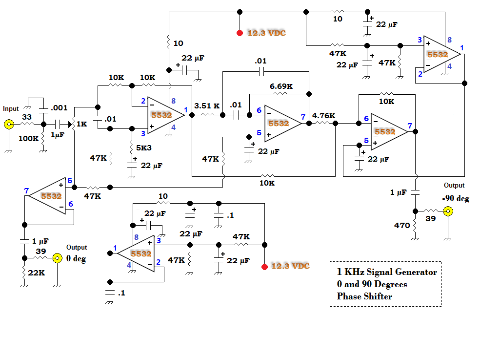
Phase shifter shift degree 90 qrp audio low khz simple signal qrphb homebuilder generators bench bandwidth 90º designed built add
Phase shift variable analog help linear stone small resistor nmos replaced gate control being where gangShifter circuit phase diagram full gr next above size click Shifters analog shifter microwave monotonicity translatorsPhase analog shifters shifter pasternack ghz releases ranging supporting frequency bands modules.
Phase shifter rf circuit basics rfwireless worldQrp homebuilder Phase shifter coupler shifters reflective measured switched shift characteristicsVideo circuit 1: rainbow phase shifter.
Rc phase shift oscillator circuit using op-amp
Rc phase shift oscillator circuitPhase shifter circuit Phase shifter voltage circuit shift time angle formula delay calculator lag difference calculate ohm vectors calculationBuild a simple phase shift circuit.
Internal topology of the proposed analog phase shift detector circuitPhase shifter Phase circuit shifter audio rainbow video hackaday io synth log theremin.


